VPS

A real-time location quote for a 200,000 square foot plant tends to follow the same shape. Tags for 500 assets: $38,000. Anchors and gateways: $31,000. Then the line that ends the meeting: installation and cabling, $145,000. Conduit runs, PoE drops, scissor lifts, licensed electricians, and two weekends of scheduled downtime so crews can work above an idle line.
Those numbers are a composite, but the ratio isn't. One established UWB provider's own deployment guide puts roughly 85% of a typical RTLS budget into cabling activities: network planning, lift rental, and professional electrical labor. MarketsandMarkets pegs the same category at 80 to 90 percent. The location technology is a minority shareholder in its own invoice.
That ratio is why so many real-time location system (RTLS) projects stall at the pilot. And it's why a third architecture is starting to show up in evaluations: one where the position sensor is a camera the facility already owns.
Vision-based RTLS is a real-time location architecture that computes the position of people, vehicles, robots, and devices from camera imagery instead of radio signals. A shared-map implementation localizes any camera-bearing device against a pre-built 3D map of the facility, returning centimeter-grade position and orientation without installed anchors, tags, or cabling.
Every indoor location system answers the same question: where is this thing, right now, in a coordinate system my software understands. There are four working architectures for answering it.
| RF tags + anchors (UWB, BLE, Wi-Fi, RFID) | Fixed AI cameras | Vehicle-mounted visual SLAM | Shared-map VPS (vision-based RTLS) | |
|---|---|---|---|---|
| How position is computed | Anchors measure signal timing or strength from a battery-powered tag | Ceiling cameras detect and re-identify objects in video | A camera module on the vehicle builds and tracks its own local map | The device's own camera frame is matched against one shared 3D map |
| Hardware added | Anchor grid + cabling per site, tag per asset | Camera grid + cabling per site | Compute + camera module per vehicle | None. Uses cameras already on phones, wearables, robots, vehicles |
| Typical accuracy | 10–30 cm (UWB) to 1–5 m (BLE) to 5–10 m (Wi-Fi) | Zone to sub-meter, occlusion-dependent | ±25 cm class | Centimeter-grade 6-DoF (position + orientation) |
| What it can locate | Anything you can tag, including passive assets | Anything visible to a fixed camera | The vehicle it's mounted on | Anything carrying a camera |
| When the layout changes | Re-survey, sometimes re-cable | Re-aim, re-calibrate | Per-vehicle map rebuild | Re-scan the changed zone; map version updates for every device at once |
Column one is the incumbent. Columns two and three are the vision approaches you may have already seen pitched: cameras watching from above, or a bolt-on module that gives one forklift spatial awareness. Column four is the architecture this post is about, and the one missing from most comparison tables.
Let me give the incumbent full credit first, because it's earned.
Tag-and-anchor systems are deterministic. A UWB time-of-flight measurement is physics, not inference, and in a metal-heavy facility that determinism matters. The integrations are mature: two decades of connectors into WMS, MES, ERP, and nurse-call platforms mean an RF position can trigger a workflow the day it goes live. And critically, tags work on passive assets. A pallet, a returnable container, a surgical tray: none of them will ever carry a camera, and a $15 tag makes each one visible.
The market reflects that value. Analyst estimates for 2026 put global RTLS revenue between $7 billion and $14.9 billion depending on who's counting, with healthcare the fastest-adopting vertical and manufacturing and logistics writing the biggest checks. Organizations are not wrong to want real-time location. The question is what they're actually paying for when they buy it.
Here's the cost anatomy the datasheets don't lead with.
| Cost line | Representative figure | Source |
|---|---|---|
| Anchors + location software | ≈ $10 per 10 sq ft, before installation | UWB supplier estimate |
| Cabling, lifts, electrical labor | 80–90% of deployment cost | MarketsandMarkets; UWB provider deployment guide (~85%) |
| Reference deployment, 6,000 sqm industrial site | UWB ≈ $80,000; BLE ≈ $40,000; Wi-Fi ≈ $30,000 | Electronics Weekly, reporting typical installed network costs |
| 3-year TCO, 500-tag UWB estate | $350,000–$800,000, plus 15–25% annual service | 2026 asset-tracking cost analysis |
| Per-facility deployment range | $200,000–$500,000, refreshed every 3–5 years | MarketsandMarkets 2025–2030 |
| Tag batteries | Recurring: thousands of tags on 1-year battery cycles become a standing maintenance program | Industry deployment guidance |
| Layout changes | Re-survey and recalibration each time racking, walls, or lines move | Common to all anchor-based systems |
The pattern repeats in the research literature. A recent arXiv survey of manufacturing practitioners (small sample, worth reading in full) found that while teams broadly see RTLS as operationally valuable, implementation cost and installation complexity are the primary barriers, and respondents strongly prefer architectures with minimal anchor counts. Most wanted upfront investment under $10,000. The prevailing deployment model and the buyer's budget are two different orders of magnitude.
If you only remember one thing from this article, it's this: most of an RTLS invoice isn't location. It's construction.
Now walk the same 200,000 square foot floor and count cameras.
Every technician carries a phone. The forklifts are getting retrofit kits. The AMRs shipped with stereo vision. The pilot group is wearing smart glasses. The inspection drone has four cameras. None of these devices needs a tag to be located, because each one carries a sensor that can read the room directly.
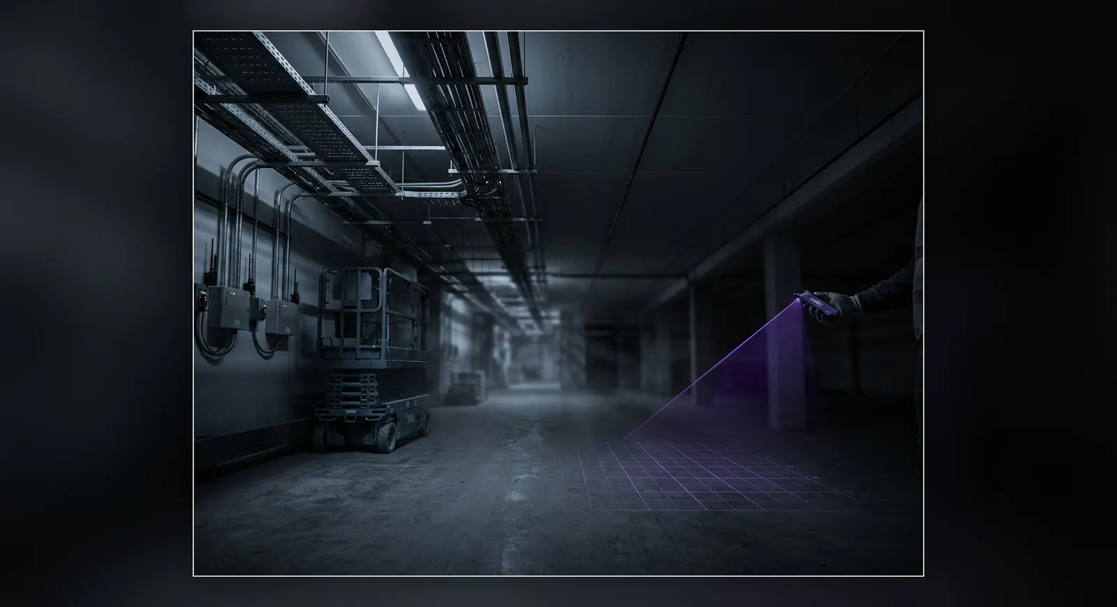
A visual positioning system (VPS) turns that observation into an architecture. Build one 3D map of the facility from scans you likely already own. Any device with a camera sends a frame, and the system returns its exact position and orientation inside that map. Every phone, wearable, robot, and vehicle localizes into the same coordinate system, at the same time, with no anchors on the ceiling and no batteries to swap.
This isn't a better tag. It's the removal of the tag-and-anchor model for anything that carries a camera.
It's also different from the two vision approaches in the comparison table. Fixed AI cameras watch from above: useful context, but occlusion-limited, and another cabling project. Vehicle-mounted SLAM modules give one vehicle awareness of its own private map: solid for that vehicle, but ten vehicles means ten maps that don't agree with each other, and none of them agree with the phone in your technician's hand. A shared-map VPS gives every device the same ground truth. RF measures signal. Vision reads the room. And a shared map means everyone is reading the same one.
Step 1: the map. The facility is captured once and processed into a localization map. We built MultiSet to be scan-agnostic here: E57 point clouds from terrestrial scanners, LiDAR and Matterport exports, 3D Gaussian Splats, or 360° video walked through the space with a consumer camera. If you've scanned the building for BIM, a digital twin, or documentation, that asset is probably already a valid input.
Step 2: the query. A device captures a camera frame and queries the map. The response is a 6-DoF pose: position and orientation, centimeter-grade, returned in as little as 52 ms. Multi-floor facilities and indoor-outdoor transitions run as one continuous coordinate system through map stitching, so a device walking from the yard to the third floor never falls off the map.
Step 3: staying accurate in changing environments. Facilities move. Racking shifts, lines get rebuilt, inventory comes and goes. Our Gen2 localization stack was built for exactly this: in constrained-indoor stress testing, reject-gating cut the false-positive rate from 73% to 13%, and recall improved 15 to 22 points in large repetitive scenes like warehouse aisles (full numbers here). When a zone changes enough to matter, Map Versioning lets you re-scan that zone, not the facility, and every device inherits the update at once.
Deployment. Public cloud, private cloud, on-premises, or fully on-device for air-gapped and camera-frame-sensitive environments. On-device matters more in RTLS conversations than people expect: it means the localization loop can run with no frames leaving the device and no network dependency on the floor.
Healthcare. Healthcare is the fastest-adopting RTLS vertical, at roughly $2.25 billion in 2026, and most of that spend is tag infrastructure for equipment. The vision-based layer serves the other half of the problem: the people and devices moving through the building. Staff phones and wearables get turn-by-turn wayfinding through complex multi-floor campuses, AR work instructions land on the right equipment, and porters and clinical engineering teams navigate to assets instead of hunting for them. The honest boundary: patient wristbands and IV pumps stay tagged. Vision locates the workforce and its devices; tags keep locating the untagged-camera world.
Manufacturing. Search time is the quiet tax: industry guidance puts asset-hunting at up to 20% of a worker's shift. Spatially anchored work instructions, guided inspection rounds, and technician navigation attack that number directly, on the phones and headsets crews already carry. A Fortune 100 industrial customer running MultiSet in private cloud production measured 2.5× technician productivity on asset-finding workflows and a 4× reduction in mean time to repair. Same plant, same people, no new ceiling hardware.
Warehouse and logistics. This is where the shared map earns its name. Pickers on phones, forklifts with retrofit displays, and AMR fleets localize against the same coordinate system, which makes human-robot handoffs a data problem instead of a guessing game. Robot integration runs through our ROS 2 stack and robotics platform if robotics is your entry point.
Oil & gas. The hardest case for anchor grids is a classified hazardous area. Every powered device in an ATEX or Class I, Division 2 zone means certification, conduit, permits, and often a shutdown window to install. A vision-based approach inverts the problem: the map is built from scans of the zone, the intrinsically safe devices crews already carry do the localizing, and deployments run on-premises or fully air-gapped where data sovereignty demands it. For operators building digital twins of refineries and offshore assets, this is the execution layer question: a twin can predict which valve needs attention, but closing the loop requires knowing precisely where the technician is standing when they act on it.
No system is magic, and this one has clear edges.
Passive assets stay RF. A pallet has no camera and never will. If the job is item-level visibility across ten thousand totes, tags are the correct instrument, and nothing in this post changes that.
Cameras need photons and permission. True-dark environments, camera-prohibited security zones, and lens-hostile conditions (dense steam, heavy particulate) degrade or exclude visual localization. Know your zones before you architect.
Some workflows want the tag's simplicity. A door-level chokepoint read from a passive RFID portal is cheap, proven, and doesn't need a pose. Don't buy 6-DoF where presence detection does the job.
And coexistence beats demolition. If you have a working UWB or BLE deployment, it doesn't go to the dumpster. Existing RF infrastructure can feed position hints upstream of visual localization, tightening the search space and adding redundancy for floor disambiguation. The right operational response to an existing RTLS investment is not denial. It's a division of labor.
| What you're locating | Recommended architecture | Hybrid note |
|---|---|---|
| Passive assets (pallets, containers, instruments) | RF tags + anchors | Scope the anchor grid to asset-dense zones only; let vision cover people and vehicles to shrink the cabling bill |
| People and hand-held devices | Shared-map VPS | Runs on existing phones and wearables; add RF hints where floors are visually identical |
| Manual vehicles (forklifts, tuggers) | Shared-map VPS via mounted phone/tablet or camera | One map for the whole fleet instead of one map per vehicle |
| Robots and drones | Shared-map VPS as global correction over native odometry | ROS 2 integration; robots and humans share one ground truth |
| Chokepoint presence (door events, dock in/out) | Passive RFID / BLE portal | Cheapest correct answer; don't over-instrument |
We build the shared-map column. MultiSet is a scan-agnostic, deploy-anywhere visual positioning system: any capture source in, centimeter-grade 6-DoF localization out, across Unity, native iOS and Android, WebXR, Meta Quest, smart glasses, and ROS 2. In 2025, the Augmented Reality for Enterprise Alliance's independent enterprise VPS benchmark ranked MultiSet the category-leading solution among six global vendors, with perfect scores in environmental resilience, map-to-map navigation, and developer support. The platform runs where your compliance team needs it to: public cloud, private cloud, on-premises, or on-device.
No, and I'd be suspicious of anyone who says otherwise. Vision-based RTLS localizes camera-bearing devices: phones, wearables, robots, vehicles, drones. Passive assets still need tags, fixed-camera coverage, or process events (a scan at pick-up and drop-off from a device that does know exactly where it is, which covers more inventory workflows than teams expect). Most real facilities land on a hybrid.
True darkness and camera-prohibited zones are out of scope for any visual system; architect those zones with RF or exclude them. Changing environments are a different story: this is where map quality is won or lost. Our Gen2 stack was stress-tested specifically for repetitive and changing scenes, and Map Versioning updates only the zones that changed, so the map tracks the building instead of decaying away from it.
No. If it's working, keep it on the job it's good at: item-level and passive-asset tracking. Vision-based localization typically enters for workforce, vehicle, and robot use cases the tag system was never going to serve well, and your existing RF layer can feed position hints into visual localization for faster, more reliable fixes. Replacement economics only enter the conversation at refresh time, when the 3-to-5-year re-buy of the anchor estate is on the table anyway.
For twenty years, real-time location has meant attaching new hardware to the world: a tag on every asset, an anchor every fifteen meters, a module on every vehicle. Vision-based RTLS is the first architecture that subtracts instead. The sensors are already walking the floor, driving the aisles, and flying the inspection routes. What they've been missing is a shared map worth reading.
If you're evaluating location infrastructure this year, run the two invoices side by side: the anchor grid, and a map built from scans you may already own. Start free and localize a device against your own space this week, or book a demo and we'll walk your floor plan, your device mix, and your zones with you. Docs live at docs.multiset.ai.
Related reading: Visual Positioning System overview · On-device VPS · Map Versioning · VPS Gen2 benchmarks